
| Home |
| Dragonnorth... |
| Modules |
| Published Source License |
| Screen Shots |
| SD Card Issues |
| Updating Firmware |
| Reference Information |
| Airflow Setup |
| Development Environment |
| I2C Addresses |
| Module Switches Setup |
| MQTT |
| LOGGER Setup |
| Processor Module Pinning |
| WattNode Modbus Adapter |
| Development History |
| Breadboard |
| Project Status |
| Software Revisions |
References
| PJRC hardware |
| ESP8266 Information |
Loading Logger Code
This page discusses how to load new firmware supplied as a binary file by Dragonnorth into a LOGGER processor module.
Contents
Programming Module Node MCU Loader Dip Switches Loading Firmware Loading ESP32 Firmware Images
Network Code Update
The LOGGER supports loading code over the internet starting with software version 1x88. To maintain security when loading code over the internet firmware can only be loaded by download from www.dragonnorth.com.
Select "Update Firmware" from the menu on a logger. The LATEST firmware is offered by default. Click the "Update Firmware" button to initiate a firmware update. Old versions can be loaded by putting the version number in the box. A typical version number is 1x88. With the version number in the box click the button to start the update. Ensure that the LOGGER remains powered until the firmware update completes. The web pages will not be active while the update proceeds.
Programming Module
The LOGGER can also be updated from a PC. Updating from a PC can recover a LOGGER that has lost power or had a bad error in a network update.
The FTDI Friend Adafruit Selectable programming Module is the recommended programmer. It can be selected for 3.3V or 5V power and pinning. It comes configured for 5 volt VCC and 3.3 volt logic levels which is the correct configuration for programming a LOGGER processor module. Drivers for the FTDI chip on this module are available at http://www.ftdichip.com/Drivers/VCP.htm.
The Adafruit Serial programming cable can also be used.
NodeMCU Loader
A copy of the ESP8266Flasher.exe program for 32 bit and 64 bit windows is bundled with the proper environment and a copy of Version 1(92)-214 of the LOGGER binary here: ESP8266Flasher.zip Download the ZIP file and unpack it into an empty directory. There should be two application files Win64ESP8266Flasher.exe, Win32ESP8266Flasher.exe a binary logger file logger1x92.bin and a Config directory. If a different version of the logger software is desired place that BIN file in the same directory. Start the appropriate (64 vs 32 bit) version of the application and perform these steps:
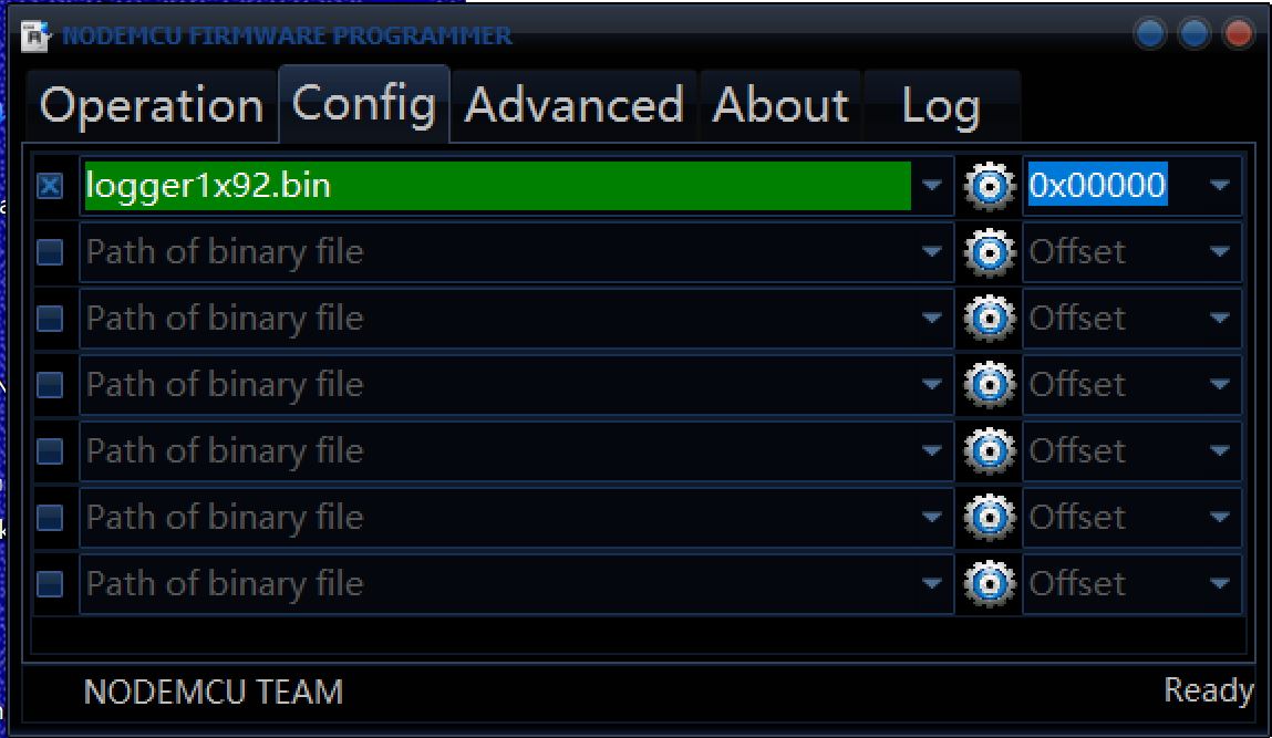
| Click the Config tab and confirm the configuration: |
|
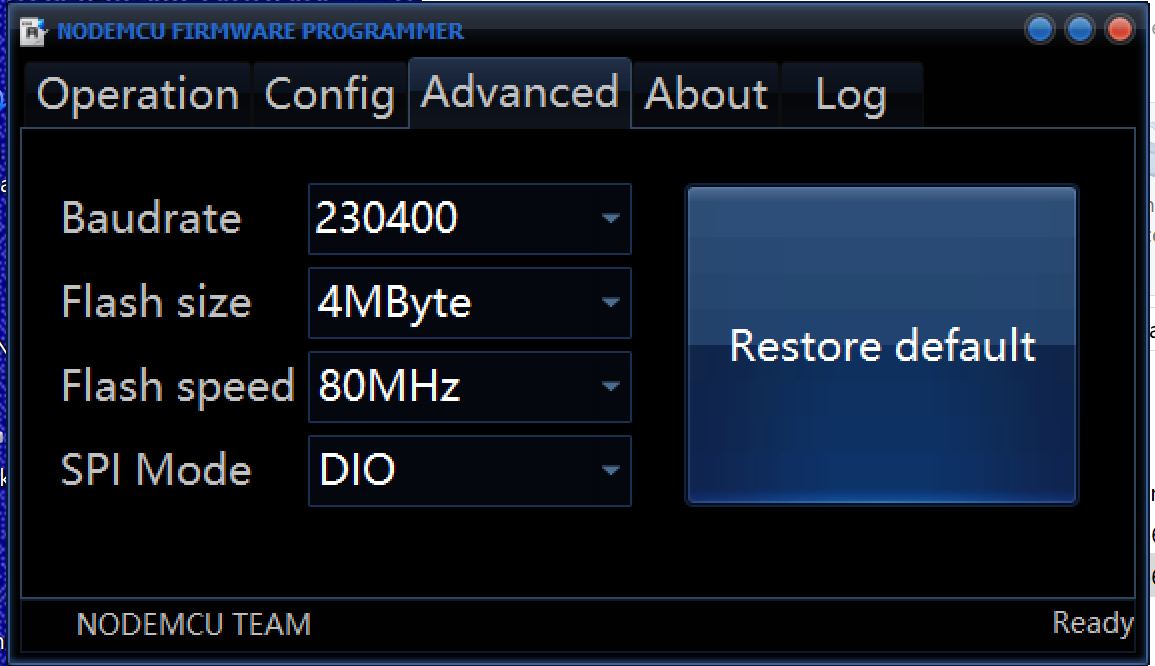
| Click the Advanced tab and confirm the speeds: |
|
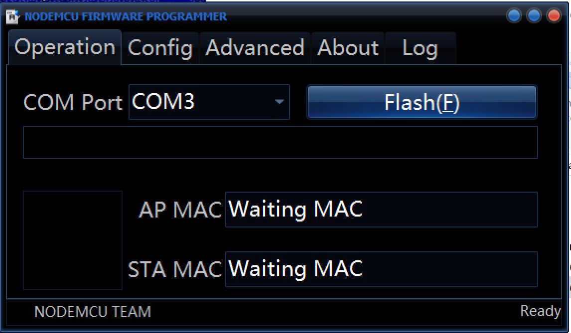
| Click the Operation tab |
|
| On the LOGGER press and hold button SW4 (right button). While holding SW4 press and release button SW2. A small green LED next to the Cat-5 connectors should now be on. | |
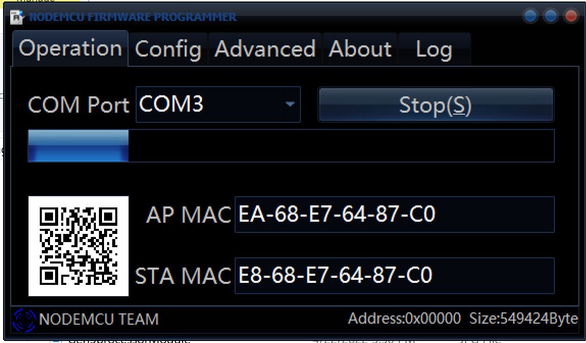
| Press the Flash button. In a few secongs the AP MAC and STA MAC fields should be filled in and a progress bar should be displayed. |
|
| Very Important Press and release button SW2 to restart the LOGGER. A green led on the ESP module should blink. NOTE: all configuration information such as the network name and password will be lost. It is possible that some of the configuration will be recovered from the SD card. |
Open source notice:
The NodeMCU flasher in the download just described is open source software and comes from Expresif. The source and program can be obtained from https://github.com/nodemcu/nodemcu-flasher. Dragonnorth is required to provide a link to the source in order to distribute this program. The source is not required to program the LOGGER module.
Dip Switches
There are no dip switches on the LOGGER processor module. When I/O modules are not being used skip this section.
The logger developers kit comes with several Sensor modules integrated on the same snap apart board. The Sensor modules are connected if the board is not snapped apart. The dip switches on the I/O and AC detector modules must be properly configured for the LOGGER to operate and for it to be reloaded see the Module Setup page for complete details.
In summary: The AC detector module should have Switch 1 and Switch 2 down. The I/O module should have Switch 1 and Switch 2 down.
Loading the LOGGER Firmware
Connect the USB to LOGGER cable to the computer and to the LOGGER.
| LOGGER processor modules four Cat-5 connectors (most common) |
|---|
| The pin closest to the Cat-5 connector is the Ground
pin.
GND on the programming cable connects to this pin. 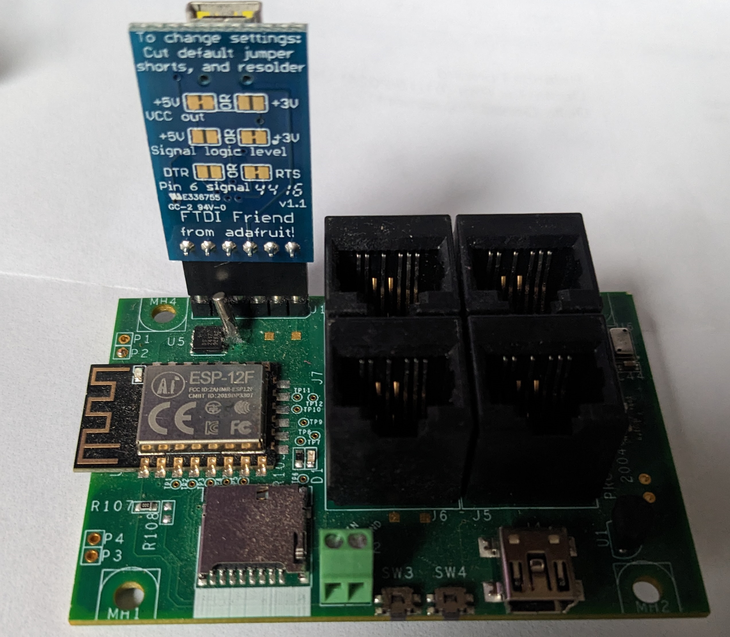
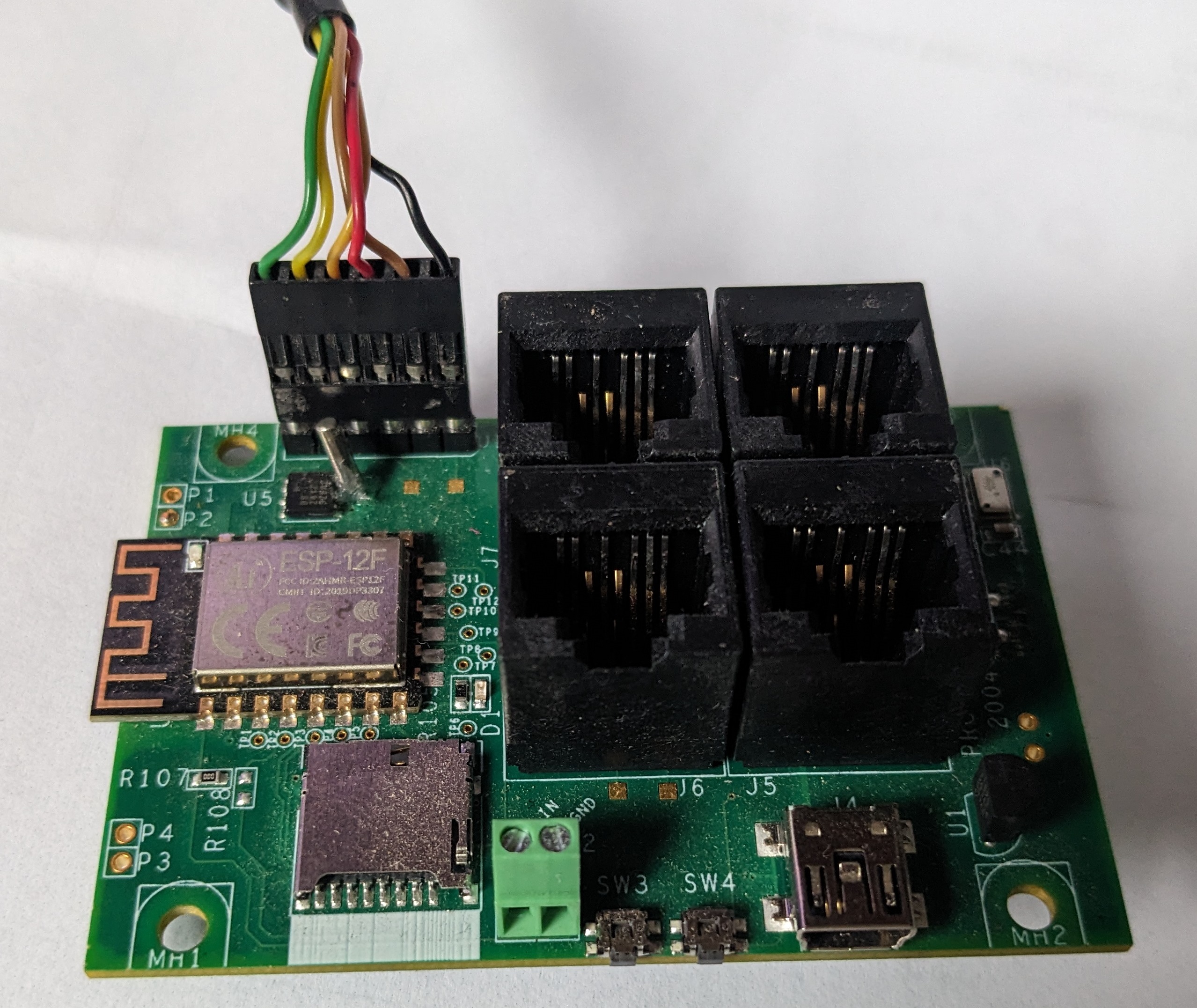
|
| LOGGER processor modules with two Cat-5 connectors |
| The J1 label on the Processor Module is the Ground pin.
GND on the programming cable connects to this pin. |
Run the appropriate (64 vs 32 bit) ESP8266Flasher.exe from that directory, a programming window will pop up. Select the appropriate COM port for your programmer from the pulldown.
Click on the Config tab. Click on the highlighted gear on the first line. In the window that opens find and double click on logger.cpp.bin. (This file should be in the ESP8266flasher directory.) This file is the image to copy into the LOGGER. Click on Open if your double click did not close the window.
On the LOGGER module press and hold SW4 a green LED will light brightly. While holding SW4 press and release SW3, then release SW4. The green LED will now glow faintly. The module is now ready to program. (On two Cat-5 LOGGER modules SW1 is used instead of SW4 and SW2 instead of SW3.)
Click on the Operation tab and click on the Flash button. The button name changes to Stop as programming starts. When programming is complete the button changes it's name back to Flash (from Stop). Loading code takes about a minute.
Once the load completes press and release SW3 on the LOGGER processor module to restart the system (SW2 for 2 Cat-5 modules). It will now be running the new firmware. NOTE: It is critical to restart the system by pressing the button to reboot it. If an automatic restart occured (as it often does) after the code download the next reboot will hang waiting for a code download. The hang might occur hours later after a watchdog timer or other event that tries to recover by rebooting.
Loading the LOGGER Firmware to an EPS32
A port of the LOGGER firmware to the ESP32 development board is in progress. Loading code to this board is similar but not quite the same. Connect the USB to LOGGER cable to the computer and to the ESP32 development board. Remove any peripherals or I/O modules connected to the board. The built in boot code depends on pins 0 and 2 floating or pulled low and some I/O modules interfere with this. A CCS811 connected to the default SPI pins has been oserved to cause a failure.
Only loading from the Arduino development environment has been tried. Press and hold the BOOT button (right of the USB connector) when the Arduino tools try to connect to the board. Once the Connected state has been reported in the lower window of the tools the button can be released.
Once the load completes reconnect and I/O modules and press and release reset button (left of the USB connector) to restart the system. It will now be running the new firmware. The LOGGER note to restart the system may apply (not yet tested): NOTE: It is critical to restart the system by pressing the button to reboot it. If an automatic restart occured (as it often does) after the code download the next reboot will hang waiting for a code download. The hang might occur hours later after a watchdog timer or other event that tries to recover by rebooting.
LOGGER Images
As LOGGER development proceeds new images will be released and placed in the list below. The latest code will always be at the top of the list. Download a new image from this list, unpack the file, and replace the logger.cpp.bin file in the ESP8266Flasher directory with the new image you want to load. The ESP8266Flasher directory was created when ESP8266Flasher was installed in the 'NodeMCU Loader' step above.
| Latest Release | Key Features |
|---|---|
| WattNode Version 1(104)-228 | Modbus Support with enhanced presentation of SlaveID. Most of the standard sensors are disabled. The logging database is specialized for logging more WattNode Modbus registers at the expense of removing most of the other sensors. The database is not compatible with non-WattNode versions. |
| Version 1(104)-228 | Modbus Support with enhanced presentation of SlaveID. |
| Version 1(103)-227 | Modbus Support. |
| Version 1(93)-215 | Improve update rate for airflow pages. |
| Version 1(92)-214 |
Updates for Differential Pressure Sensors. Add Airflow pages. |
| Version 1(88)-210 |
Support for Differential Pressure Sensors. Preliminare support for WattNode MODBUS devices. |
| Version 1(60)-158 |
Allow Named Periods to contain spaces. Add temperature in Fahrenheit. |
| Version 1(59)-157 |
Support for Named Periods. |
| Version 1(58)-155 |
Over the Network Code Updates Water Flow Reporting Direct Links to Sensor Types Clock Chip Support (LOGGER with 4 Cat-5 connectors required) |
| Out of date releases | |
| Version 1(42)-112 | |
| Version 1(40)-110 | |
| Version 1(38)-108 | |
| Version 1(37)-107 | |
| Version 1(34)-104 | |
| Version 1(33)-103 | |
| Version 1(31)-101 | |
| Version 1(30)-100 | |
Send comments and corrections to:
Webmaster: mnewman@dragonnorth.com